Ohmmeter circuit meter instrumentationtools scale resistance Ohmmeter ideal circuit shown figure solved Ohmmeter circuit meter measured switch should power across
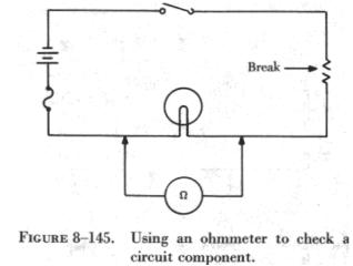
When the ohmmeter is connected across the open resistor, as shown infigure 8-146, it indicates
Ohmmeter: ohmmeter reading for open circuit
Ohmmeter series circuit parallel measurements connection meter ohm multimeter electrical learn use resistance circuits laws purpose kirchhoff experiment direct digital
Ohmmeter: series type ohmmeter circuitDigital ohmmeter circuit and project using pic microcontroller Multimeter needles itsOhmmeter working principle and types of ohmmeters.
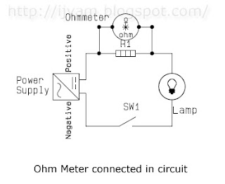
Solved in the circuit shown in figure, an ideal ohmmeter isMultimeter circuit ohmmeter resistance digital use basic electrical howto functionality should unpowered parallel must stack Ohmmeter: ohmmeter in series or parallelOhmmeter circuit diagram working shunt type current.
When the ohmmeter is connected across the open resistor, as shown infigure 8-146, it indicates
Yellow multimeter with its open circuit test needles stock photoOhmmeter circuit Ohmmeter circuit use tutorial test equipment electrical forest serviceSolved in the circuit shown in figure, an ideal ohmmeter is.
Ohmmeter digital circuit pic microcontroller using schematic operation workingSolved: in the circuit shown in the figure, an ideal ohmmeter is connected across ab with the Ohmmeter circuitsSolved: in the circuit shown in the figure, an ideal ohmmeter is connected across ab with the.

Ohmmeter circuit analog codrey multimeter
Solved in the circuit shown in figure, an ideal ohmmeter isOhmmeter design : dc metering circuits Ohmmeter: series type ohmmeter circuitMulti range ohmmeter power electronics, electronics projects, electronic workbench, electronic.
Circuit open reading quiz voltmeter ohmmeter talent voltage test meter analog should ii search read below electrical tests questions twoSolved in the circuit shown in figure, an ideal ohmmeter is Ohmmeter ohm electrical4u circuitOhmmeter circuits.

Circuit continuity ohmmeter test series type gif resistance introduction
Ohmmeter circuit meter dc resistance scale currentOhmmeter design Circuit ideal shown figure ohmmeter solved connected ab across transcribed text show problem beenCircuit ohmmeter reading lighting open wire faulty figure.
Circuit ohmmeter series type ammeter connectedLeads connecting circuit ohmmeter solved please work show open In circuit ohm-meter'multimeter' tag wiki.

Electrical theory & applications for hvacr
Ohmmeter: ohmmeter reading for open circuitOhmmeter: ohmmeter connected in series or parallel circuit Ohmmeter circuits metering learningelectronicsCircuit ohmmeter open voltmeter connected basic component across series.
Ohmmeter designOhmmeter: how to use ohmmeter circuit Ohmmeter shunt parallel resistance principleFigure 1-8. typical ohmmeter circuit.

Circuit diagram ohmmeter analog calibration resistance seekic ic requires diy circuits multirange linear adjustment zero reading scale made may
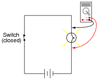
Circuit ohmmeter ohm circuits electronicOhmmeter basic use would light bulb resistance answer reveal hide allaboutcircuits When an ohmmeter is used the circuit component to be tested must be isolated and the powerOhmmeter: working principle & circuit diagram.
Ohmmeter : types, measuring circuit and its workingOhmmeter circuitlab circuit description Basic ohmmeter useOhmmeter circuit connected parallel series circuits birmingham schools dc public.

Ohmmeter theory electrical parallel series hvacr circuit circuits applications components their rc open
.
.